By Duncan Louttit October 2017
By Duncan Louttit October 2017
When you organise a proper competition you need reasonable timing equipment to avoid dispute. Hand timing relies on a certain amount of trust and goodwill and this can be difficult in the "heat of battle". For development, I use the facilities of the mouse itself to see how long it took to finish the challenge; it's a lot easier and less effort. For those who need to run a competition, here are some notes on the timing gear we recently built. This information is supplied "as is". I take no responsibility for its completeness or accuracy and I take no responsibility for any use you make of it. It has not been prepared for professional presentation.
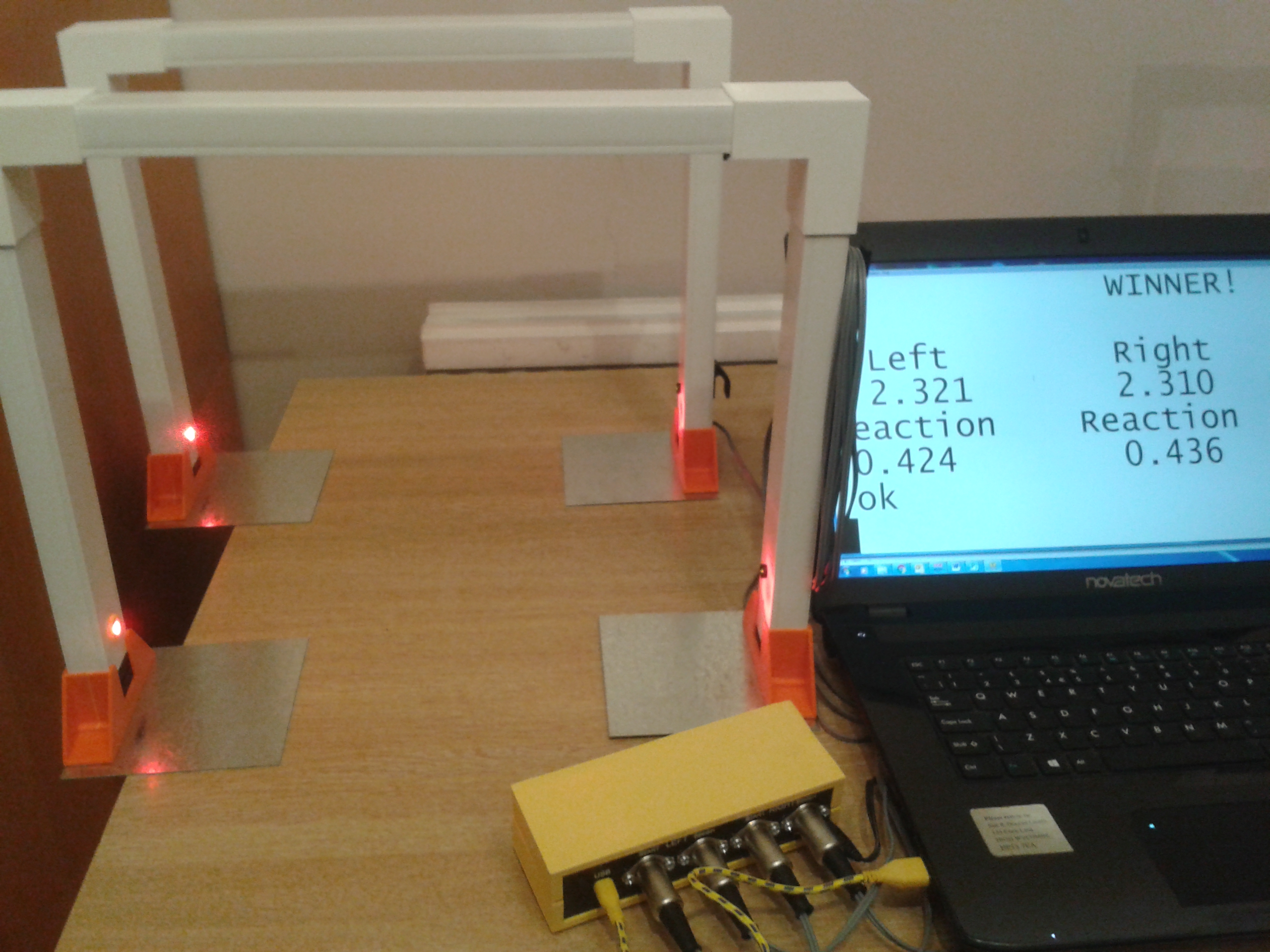
The hardware is a set of four gantries to stand over the course. They are made of electrical conduit approximately 40mm by 25mm. The 90 degree joiners are 3D printed in ABS. The stands are 3D printed in ABS as well. They are glued to plated steel squares to form a stable base. The steel sheets slide under the course for drag racing and sit on the course for line following. There are spacers to raise the gantry when it is used for drag racing. These are also 3D printed. There are 3D printed cleats glued to the sides of the gantries for the long leads to be wound onto for storage. The conduit is glued to the various 3D printed parts using plumbers pipe adhesive. DON'T GLUE THE CONDUIT TO THE STANDS OR THE SPACERS. You will need to take these apart to allow the drag racing spacers to be fitted. The following from Bernard Grabowski:
Instructions:
Manufacture by 3D printing in ABS, I used CEL Robox Tech ABS which is dimensionally stable.
Complete Elbows for the gantries are made by gluing 2 x Half-Elbows together with acetone.
Holes have been provided for dowels made of 1.75mm 3D printing filament to align the two halves.
Complete Bases for the uprights are made is a similar fashion from two Half-Bases.
A total of 16 Half-Elbows and 16 Half-Bases are required for a set of 4 gantries.
To increase stability, it is recommended that each Base is fixed to a steel sheet approx 120mm x 120mm x 1mm thick using an epoxy adhesive. I used Araldite.
Back to me (Duncan)
On one side of the gantry there is a 4mm diameter hole 25mm from the bottom. This forms a "pinhole" for the photodiode sensor. The sensor PCB assembly is mounded on the other side of the conduit to give a spacing back from the hole of about 22mm. A green LED is mounted above the hole to show when the light beam is clear.
The sensor is a dual op-amp forming a photodiode amplifier followed by a comparator to give reasonably fast transitions. Everything is run from a 3V3 power rail to ensure compatibility with the Nucleo.
On the other side of the gantry there is a tophat LED holder printed in ABS. A very bright LED is mounted here to shine on the pinhole for the sensor. This is fed via a 56R resistor from a 5V supply. The leads to the LED are run inside the conduit to the sensor side and thence in a cable to the timing device.
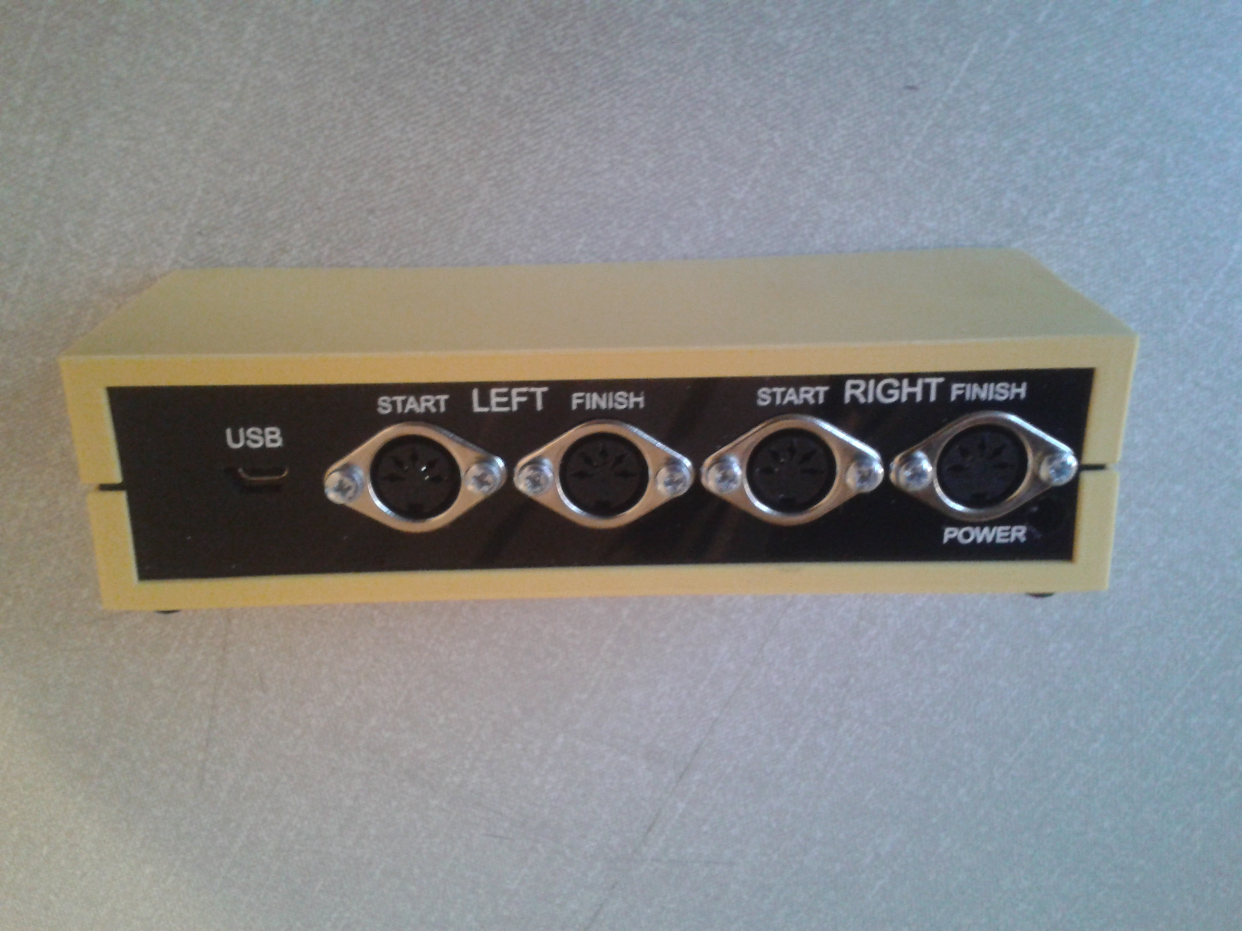
The leads from the four gantries are taken to the timing device via 4 way cable. The wires are for ground, 3V3, 5V and signal. Inside the timing device they are taken to the relevant power levels and individual I/O pins of a NUCLEO development board. The Nucleo boad has a USB connector to couple it to a PC. This is used to program the processor and also as a serial link. There is a wallwart 5V power supply for the LEDs as these need 50mA each to get the desired brightness. I didn't want to rely on the USB power for this. The Nucleo board is powered from the USB connection. The casing for the timing device is made from two 3D printed pieces and two laser-cut pieces.
The PC uses TeraTerm to communicate with the timing device. The serial link runs at 115Kbaud. The timing device does all the formatting on the screen using VT100 cursor control commands. TeraTerm should be set with a big font for maximum visibility.
The firmware is written in FORTH using the free LITE version from MPE. See http://www.mpeforth.com/software/forth-cross-compilers/forth-7-cross-compilers/lite-cross-compilers/ for more details. There are two tasks. One just scans the sensors and notes the time, in milliseconds, when the sensors are blocked. The other task reports these times on the screen and handles drag race countdown etc.
I have included the design files. There are Gerbers for the sensor PCB. I used OSH Park to get the prototypes made. There are STL files for the various 3D printed parts. These were printed on a ROBOX. There is a partslist. I think you can get all the parts from Farnell. I have also included the FORTH source files for the firmware and the hex file for programming the NUCLEO board.
I would like to thank Bernard Grabowski for designing several of the 3D printed parts and coming up with the general mechanical arrangement.
I would like to thank Stephen Pelc of MPE for making FORTH LITE available for non-commercial purposes.
Documentation files:
timer sensor.zip Gerber files
base - generated by Pro_DESKTOP Version 8.0 (repaired).stl
casing - generated by Pro_DESKTOP Version 8.0 (repaired).stl
LED mount - generated by Pro_DESKTOP Version 8.0 (repaired).stl
spacer - generated by Pro_DESKTOP Version 8.0 (repaired).stl