This is a quick review of my experience in trying to achieve simple low-cost range sensing.
What I, and possibly everyone else, want, is a non-contact range sensor that will give an 8-bit number corresponding to the range to a wall. The range should be in mm (0-255). The sensor should be reasonably linear or at least monotonic. It should be updated at least every 5 ms (10mm at 2m/sec). It should be completely unaffected by sunlight and Techno Games lighting. It should be unaffected by likely changes in wall reflectivity (+/- 50%). It should be reasonably easy to make and calibrate and cost less than £5.00. Phew!
1) Use a PSD with slits instead of lenses.
2) Use the amount of reflected light and somehow compensate for the effect of changing wall reflectance.
For either approach, you must use modulated light and filtering to remove ambient light problems. For either approach, I strongly recommend visible light, as it makes it easy see exactly where the light spot is on the wall. It is difficult to get a range from a spot shining over the wall or down on the floor!
I also recommend that you use the narrowest angle LED that you can find. With a slit, this determines how much of the light is used. With the reflective system, it determines the "footprint" of the sensor on the wall. It is quite difficult to use the second approach when some of the light spills over the top of the wall. If the spot size on the wall is wider than the width of a post, you can get very misleading results. Many IR LEDs have a half-angle of 20 degrees or more. This means that some of the light must miss the wall at ranges of more than 68mm and some of the light must miss a post at ranges of 16mm or more. The narrowest beam of IR LED that I could find in Farnell is 10 degrees.
For these reasons, my favourite LED is the Agilent HLMP4101. This is red, with a beam angle of 4 degrees.
I spent a lot of time trying to make this work and failing. There are several issues. Firstly, making fine accurate slits is not easy. Positioning these slits in relation to the LED and PSD is also not easy. Because of the high-resistance layer on the PSD, they are not very sensitive. This, together with the light lost because of the slits, meant that I could not achieve a reasonable maximum range. I gave up.
A crude system just measures the amount of light reflected. This can obviously be made to work (e.g. Cyclops) but it needs calibration for the individual maze and can have large errors if walls of different construction appear in the same maze. To give some idea of the problem, I measured a difference of 20% in the light reflected from a painted maze wall and from a piece of normal photocopy paper at the same range. A step range error of this size when moving through a maze at high speed will probably cause problems.
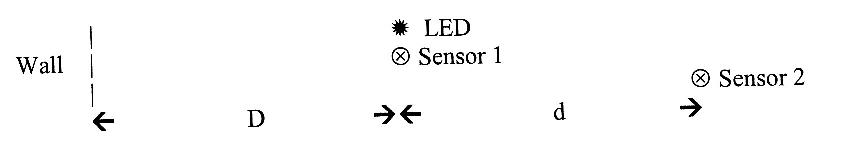
My system is to use one LED and TWO sensors at different positions. The sensors have wide "seeing angles" so that both of them see the entire light spot on the wall. The two measurements allow you to correct for the reflectivity of the wall.
The light intensity at a point from a normal (non-laser) source varies according to the square of the distance from the light source. (Inverse square law). I assume that the spot of light on the wall is just such a source. As, in theory, all the light from the LED, is scattered by the wall at the spot, there is no change in the amount of light scattered back from the wall provided all of the spot is on the wall and each sensor can "see" all of the spot.
Let the wall be "D" from one sensor and "D+d" from the other (sensors "d" apart). Then the measurement at the near sensor is proportional to D2. The measurement at the far sensor is proportional to (D+d)2. The ratio of the measurements is then D2/(D+d)2. So:
M=D2/(D+d)2
vM=D/(D+d)
vMd=D-vMD
vMd=D(1-vM)
D=d/(vM-1)
So the calculations needed are a couple of divisions and a square root. This is well within the capabilities of a typical 8-bit processor in a couple of milliseconds.
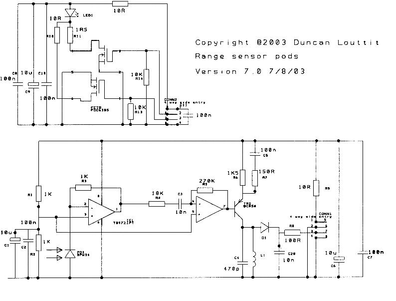
I spent a lot of time on this. Currently I am on version 7. I learnt a lot about the problems of sensing small amounts of modulated light in high ambient fluorescent light. Here is some of that knowledge.
I settled on large-area silicon diodes. I have used Siemens SFH206K and Temic BPW34 with (eventually) some success. You need a wide viewing angle to ensure that all the light spot on the wall is "seen". You need a fairly fast response to use the techniques that I used.
The load for the diode is crucial. I tried a simple transistor gyrator circuit to simulate an inductor. This was not good. It did filter the 50Hz signals BUT it modulated the 50Hz onto the desired signal so that it could not be removed. I tried a proper passive tuned circuit with similar results. The impedance of the photodiode changes with illumination and again modulates the desired signal. The same applies with simple resistive loads.
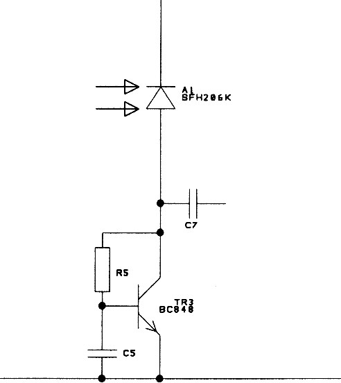
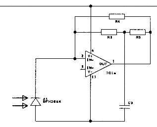
The best solution that I have is to feed the diode into the virtual earth point of a fast, low-noise op-amp. I tried different filtering feedback systems but, possibly due to gain-bandwidth limitations, I ended up with a simple inverting amplifier. The feedback resistor has to be very low to cope with the diode current in direct sunlight. This current is of the order of a couple of milliamps.
Filtering
Not surprisingly, the bigger the difference between the light modulation frequency and the ambient light frequencies (say up to 100Hz) the easier the filtering is. I eventually settled on 500KHz, but I will move to half that when I get time. At these frequencies, the easiest and cheapest filter is a conventional tuned circuit. The final system has some low-pass filtering as well.
My early systems used separate measurements for the near and far sensors. For each measurement, I pulsed the LED and did an A/D conversion. Each measurement took a few hundred microseconds. The problem with this is that, if there is any intermodulation from the ambient light, the two measurements are affected by different points in the interference cycle and the ratio of the measurements is affected. I solved this problem by using reservoir capacitors in both channels to hold the signals for successive A/D conversions. To discharge the capacitors, I configure the A/D inputs as outputs with a zero on the pin. This clamps the signals between LED pulses.
The LED driver allows me to drive the LED at two different current levels. When the wall is close, say 10mm, you get 100 times the signal from when the wall is at 100mm (in theory). The system must have a wide dynamic range. I generate the pulse train for the LED under program control. I can vary the length of the pulse train to further change the effective size of the signal from the LED.
I chose to put the two sensors about 25mm apart.
The results
The current best system allows me to make consistent measurements in direct sunlight or directly under a fluorescent bench lamp. I think I have solved the ambient light problem.
Here are some raw results with different targets and different LED drive at a fixed distance of 40mm. There are data sets for my painted wall and normal white copier paper and low and high LED drive current. The data is for the near and far sensors.
|
Paper |
Paint |
||||||
|
Low |
High |
Low |
High |
||||
|
near |
far |
near |
far |
near |
far |
near |
far |
|
365 |
301 |
786 |
651 |
447 |
368 |
958 |
798 |
|
364 |
301 |
789 |
652 |
445 |
374 |
955 |
800 |
|
363 |
295 |
792 |
657 |
443 |
364 |
953 |
798 |
|
364 |
295 |
787 |
652 |
442 |
368 |
955 |
804 |
|
363 |
295 |
791 |
656 |
438 |
369 |
954 |
795 |
You should note that I use a 10-bit A/D. The paper reflects about 20% less light than the paint. The high current drive to the LED gives a bit over twice the light. The important point is that these numbers came from the sensors under bright fluorescent light and there is not much noise.
Here are some graphs of averaged raw (5 samples for each point) data.
You can see that at distances of less than 20mm, the far sensor could not see all the spot of light. You can see saturation effects at close distances with high LED drive.
Here is a plot of the ratio of the two measurements.
You can see that the ratio changes usefully for distances from about 25mm to 60mm. You can see that high drive to the LED is only useful at larger ranges. The most significant fact, though, is that the ratio is the same for paper and paint finishes.
It is possible to do useful optical range sensing without lenses. You can get reasonable accuracy up to at least 50mm. Beyond this, life gets difficult for reasons I don't understand. The figures do not support a square law for the dropping off of light intensity. I shall need to do further work to identify the problem. It may be something in my circuitry or it may be something more difficult to deal with, such as a side-lobe of the LED light pattern being reflected from the floor.