Sorry about the quality of the diagram, it is the best I can do.
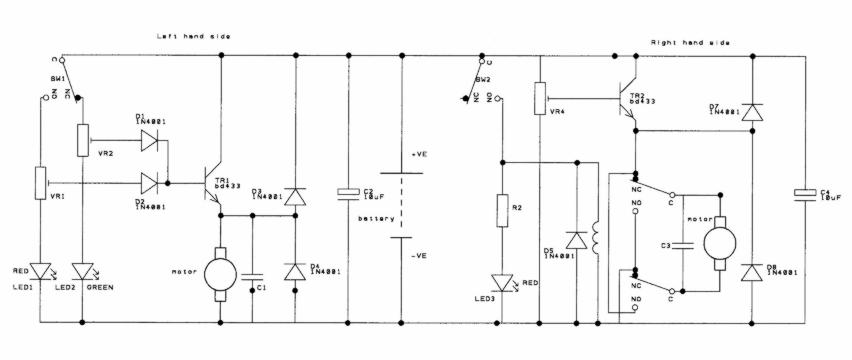
The relay on the right hand side simply reverses the direction of the motor rotation. The red LED is to show you when the microswitch hits something. The transistor is to buffer the trimmer potentiometer so that it doesn't have to carry the motor current. The trimmer allows you to set the motor speed from stopped up to (very) fast. The capacitors and diodes are simply to suppress the motor so that arcing in the commutator doesn't cause interference. Make sure that C3 is mounted as close as possible to the motor.
The microswitch on the left hand side selects which of the two trimmer potentiometers set the speed for the left hand motor. D1 and D2 are steering diodes so that the trimmers don't interact with each other. The LEDs show you which trimmer is active so that you don't adjust the wrong trimmer. You should ensure that they are mounted near to the relevant trimmer.
last modified 14/9/01