This is a prototype of a system for controlling the speed of a DC motor used for one side of a micromouse. While complete details are given, it would require considerable modification to be used in a real mouse.
The basic principle is similar to a child bowling an old-fashioned hoop along. When it slows down too much, the child gives it another push with a stick to bring the speed back up.
BESS C applies full battery power to the motor for a short time (~20ms) then waits until it slows down below the desired speed. When it does slow down enough, BESS C gives it another full-power pulse. In its simplest form, the motor pulses are fixed-length and the time between them varies to adjust the power applied to balance the load.
BESS C has a P power FET to apply the power to the motor. While this is on, the motor terminal voltage is determined by the motor speed and the drive current to the armature. Speed sensing at this time is problematical to say the least. When the FET turns off, there is quite a lot of inductive ringing before the motor terminal voltage settles to the back-emf generated by the motor at the speed it is running at. BESS C ignores the motor emf for this period. On the motor used, this takes less than 1ms. After this time BESS C can monitor the voltage with some confidence.
For the prototype, the motor voltage is measured with the analogue comparator built in to the processor. The only information needed is whether the voltage is greater than the set point, so a comparator is ideal. More complex versions would use some kind of ADC. For the prototype, the speed setting is made by adjusting a pre-set. In a practical situation, this would be replaced with a voltage from a master processor or a proper ADC would be used so that the set speed can be set in software depending on the mouse position etc.
The full circuit is slightly more complex. As a mouse needs to be able to slow down more rapidly than just rolling to a halt, I have implemented a braking system. This is the N power FET across the motor. Each of the FETs has a parasitic diode that acts to clamp the motor voltage between the battery voltage and ground. This helps to minimise the inductive ringing phase. There are also suppression capacitors to help reduce EMC problems.
The feed to the analogue comparator has a simple RC network to reduce the commutator noise from the motor. The time constant here must be short compared to the time allowed for inductive ringing or the processor will "see" the ringing stored in the RC network.
The battery used is 6V as 5V was not quite enough to turn the FETs on properly. (OOPS!). The processor is rated to 6V so it is O.K. Note the decoupling between the processor and the battery to minimise interference from the commutator.
The processor is an Atmel AVR 2313. This is quite cheap and has vastly too much processing power for the application, but it can be programmed in FORTH via an ISP lead for interactive debug. This makes the software development trivial.
If I was starting again, I would add pull up/down resistors to the gates of the FETs so that they are guaranteed to be off when the processor is in a reset state. As they are, they have been overheated a couple of times when both FETs were on at once!
The software is written in MPE's AVRAM FORTH. This is an incremental and interactive software development system using In System Programming to program the flash memory in the microprocessor. It is quite expensive. There is a cheaper system from MPE for the 8051 called a FORTH Stamp that gives similar facilities for under $100.
The main loop has 5 phases. The first phase ACCELERATE, is when the motor is turned on. There is a variable ON-TIME which holds the length of the on pulse in milliseconds. ACCELERATE simply turns the motor on, waits for ON-TIME milliseconds and then turns the motor off. The 1 millisecond delay for inductive settling is also part of the ACCELERATE phase.
After the ACCELERATE phase there is ?MOREPOWER. This is to adjust the length of the on pulse if it is much too short. ?MOREPOWER checks to see if the speed is already too slow. (Remember that this is only 1 millisecond after the power pulse). If it is already too slow, the motor pulse was not long enough. ?MOREPOWER increases the on pulse length by 1 millisecond up to a maximum of 40 milliseconds if the motor was too slow. The rate of increase and the maximum length are adjustments that should be made in the light of the inertia of the mouse under control.
After the ?MOREPOWER phase is the CRUISE phase. This is basically a time delay during which the motor should normally slow down to the level at which it needs a further pulse. It is a 10 millisecond delay that is terminated if the motor speed drops below the threshold. The length of this delay is another adjustable value.
After CRUISE comes ?LESSPOWER. This is to adjust the length of the pulse if it is too long. If the motor speed is still too fast after the CRUISE phase, the motor received too much power during the last power pulse and the pulse should be shortened. ?LESSPOWER can reduce it by 2 milliseconds down to a minimum of 1 millisecond. Again this 2 millisecond change can be adjusted to suit.
After ?LESSPOWER comes BRAKE. If the motor is still running too fast at this time, then the motor must be braked. BRAKE does this by turning the braking FET on in 2 millisecond bursts, with 1 millisecond settling times between them, until the speed is slow enough. Basically, BRAKE is the opposite of the rest of the system. In the main system, the motor is given power pulses if it is too slow. During BRAKE it is given braking pulses until it is slow enough. In a system where the set speed only changed slowly if at all, there would be no need for BRAKE but in a mouse you need to be able to slow down rapidly at the approach to corners. This is BRAKE's function. In a fully integrated mouse, it may be better to use a separate braking function when the speed has to be reduced and use a simpler speed controller between braking states.
After BRAKE the controller just goes round again. The various times need to be adjusted for the particular conditions of the mouse and can be fairly critical. The whole system behaves somewhat like a switched mode voltage regulator and the inertia of the mouse behaves like the inductor in such a system. Because the inertia has a big effect on the time constants in the control system, there is no way that a generally useful set of numbers can be given. The numbers in the current system have had a small (about half an hour) amount of optimisation for a virtually no-load system at a variety of speeds. I make no claims for them being near optimal.
I have not done any mathematical analysis of the system but I suspect that it may be possible to come up with some design equations for it. Unfortunately, these will include mouse constants that are difficult to measure. For example the effective inertia of the mouse is almost certainly different when it is driving in a straight line than when it is turning. Also if one wheel slips the inertia seen at the other wheel will change dramatically! Because of this I don't think it is worth any great effort in analysis. I would recommend however that, if you want to use one of these, that you spend some time "playing" with it and observing the waveforms on an oscilloscope. You will soon find where the loop starts hunting and get some idea of the response times of the loop.
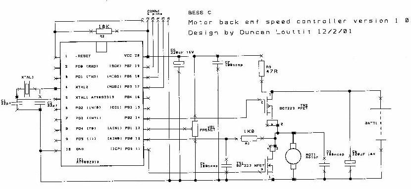
This shows the "normal" state with no braking. The bottom waveform is the drive to the PFET. When the voltage is low, the FET is ON. This shows on pulses of approx. 1 millisecond about 8 milliseconds apart. The upper waveform shows the motor voltage.
During the on pulses the motor voltage is nearly the battery voltage. When the FET turns off the voltage drops sharply to just below 0V where it is clamped by the NFET parasitic diode. Recovery from this inductive spike takes about 0.5 milliseconds. From then on the motor is idling. The voltage varies up and down as the armature rotates relative to the fixed magnets. Remember that this is a 3 pole armature. The spikes are probably due to the commutator segments. The voltage gradually drops until it is low enough to trigger another power pulse.
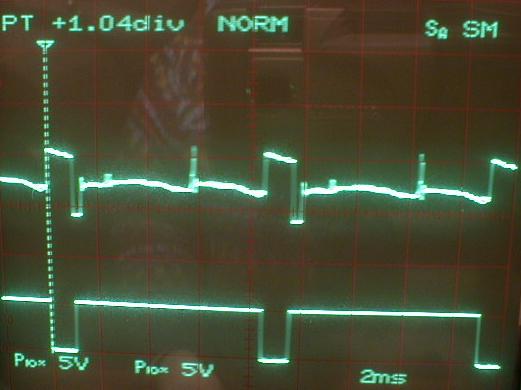
This shows the braking system. The power pulses double because a single 1 millisecond pulse did not increase the speed sufficiently so the software gave it another, longer pulse. After the second pulse there is the 10 millisecond cruise period when not much happens. Then you can see 8 braking periods where the motor voltage is clamped to 0V by the NFET. At the end of each braking period you can see an inductive spike upwards where the FET turns off and the armature current has nowhere to go. The last of these spikes is quite small as the motor is hardly moving and there is very little generated current.
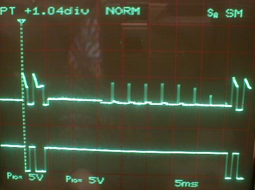
This photo shows that the system has not been optimised for this low-speed low-load situation. The brakes are applied on every cycle. Because the brakes have been applied the motor pulse is reduced in length. The short pulse was not long enough to speed the motor up sufficiently so BESS C gave it another, longer, pulse. This puts in too much energy so the speed doesn't fall quickly enough and the brakes have to be applied again. It is possible that the minimum motor pulse should be a little longer or the pulse should not be shortened by so much when the motor is too fast at the start of the braking phase.
BESS C is a useful controller. It is very similar to the system used successfully in THRUST SSM. It uses few components and there is no need for any heatsinks. It does let the mouse know what speed the motor is turning at without relying on interrupts or timing within the mouse.
It has some limitations however. The main one is response time. It cannot change speed at a high rate (especially braking). The other limitation is that tuning it is by "suck it and see" rather than analysis.
I will probably only use the system for very simple mice where I want to get the absolute minimum component count whilst still having useful speed control.